Today I decided to fix my front panel USB , that were since long gone due an unspecified issue on my Asustek mobo (WYGIWYP, what-you-get-is-what-you-paid). Since the usual remedies wouldn’t work (resetting CMOS, changing front panel, BIOS fiddling) I decided to tackle the problem the hard way, by bypassing the motherboard completely.WARNING: please, please see, read and understand the DISCLAIMER. Playing with USB is dangerous, as shorthing out the 5V+ will surely blow up (something valuable in) the computer. I advise against following those instruction.
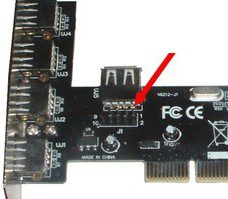
Update(22/10/12): I noticed there are PCI USB adapters that come with a 9pin header, that should be even more suitable to this operation, I wonder if it comes with the standard pinout for USB front panel headers. Better check before use…

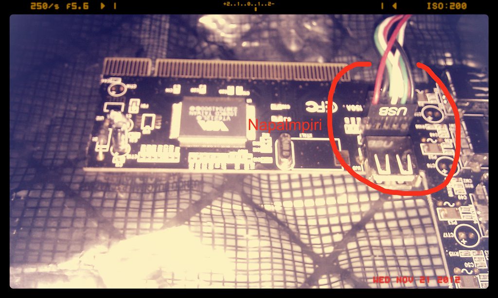
I got hold of an Eminent EM1105, a 4+1 Ports PCI USB Adapter 2.0 but I strongly suspect other similar cards would work. This handy card has a Jumper (J6) just below the internal USB port. It came handy for me to connect one of the front panel connections to this Jumper.

Finding the Pinout of the J6 jumper in a given card isn’t hard, with access to a multimeter and a a piece of usb cable with exposed cable un a side
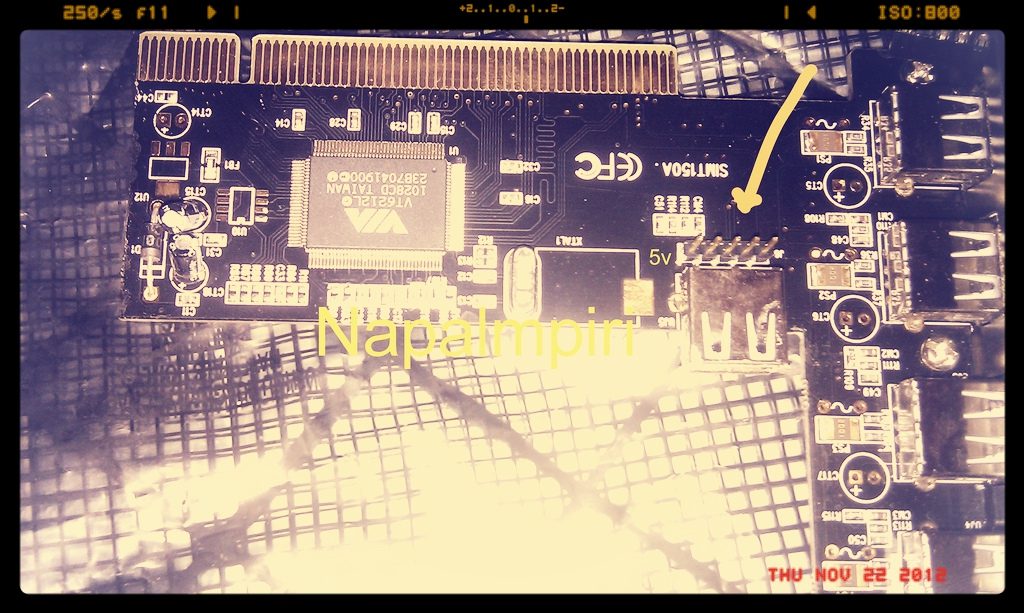
The J6 Jumper in my card had the following pinout.
From left, counting from the first pin marked with 5V, I have
[+5v NC D- D+ GND]>
Before powering up everything I double checked with the multimeter which front panel connector would work (just one will work, the other one will be left dead) and by measuing with the multimeter from the external USB body to the J6 jumper I can assest if the panel port is connected how it ought to be. Of course measuring a sensistive electronic device with a multimeter may be dangerous for the electronic device.

…but I prefer to avoid to blow the entire thing in smoke and fire should the +5V come into gnd, how it would just reversing the connection entirely or failing to grasp the orientation or just plaing having a different PCI card with a different routing and a different pinout for J6. Anyway the PCI card sort of survived, and it’s working fine.
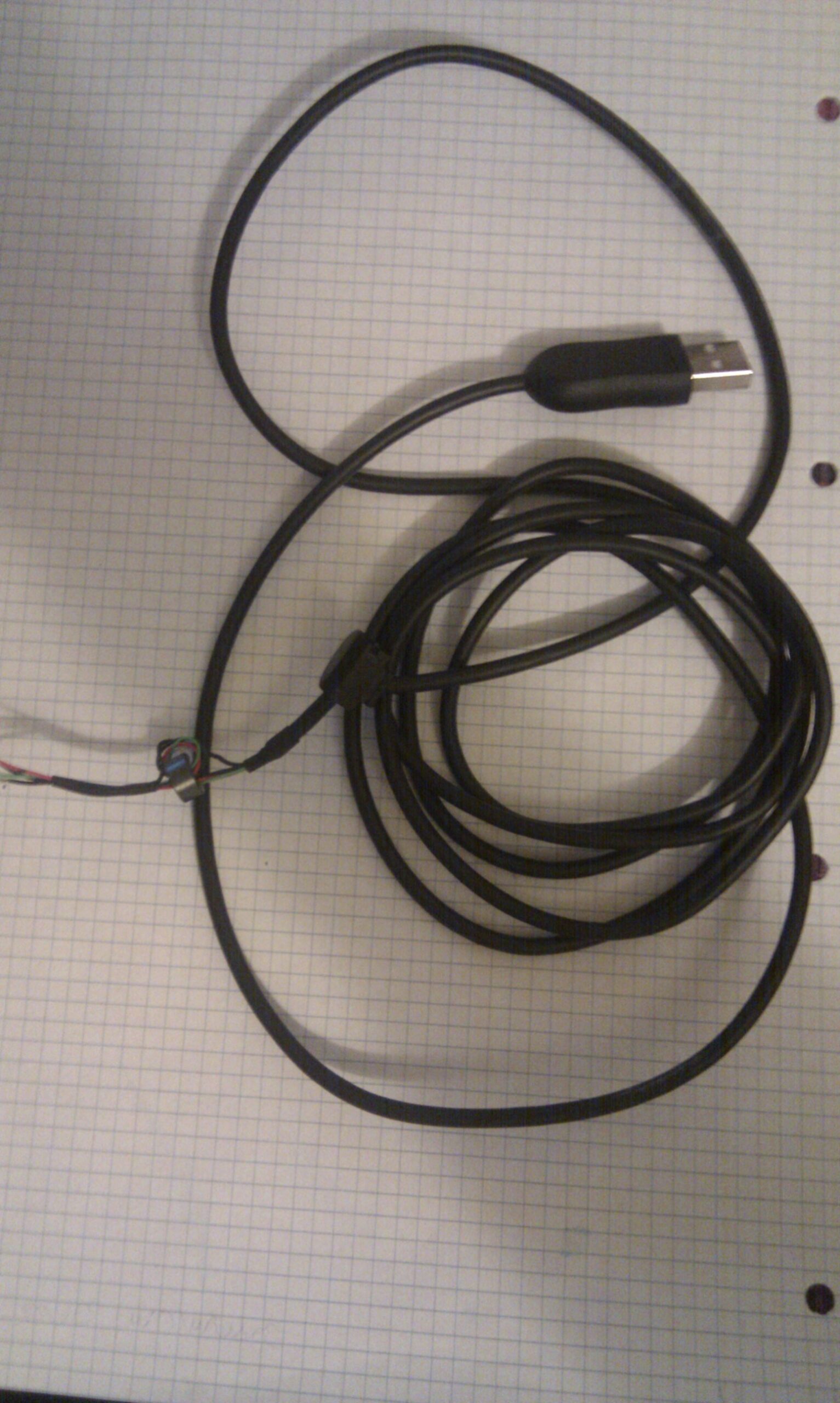
To access the USB port internals with the multimeter probe, without touching the grounded usb chassis port, I used an old USB keyboard cord: so I am sure I am not touching the ground usb body with the multimeter probe while measuring.

Bonus: the exposed cable coming from the usb connector has colours, usually corresponding to the right signals, so it’s easy to see if I am measuing D+ (green, in my cable) D- (white in my cable) or ground and +5V. The exposed cable is intended to be used with no power around. If the red and black wire even briefly touch while everything is powered on, the PCI card and optionally the PCI slot will sing Goodbye-goodbye and wait for you in the paradise of unlucky gear.
