I have a few baofengs I don’t use, as I prefer going around with my Yaesu. My QRP rig set is centered on my Yaesu, in fact. But there are times when I am not very confortable with losing or damaging the Yaesu, and being able to carry a Baofeng would be nice. But the harmonics! Aw!
Now, once I got my SDR radio I had the chance to look in a very non-scientific way to the harmonics of those Fengs and decided that I would be funny to have a few filter and try to clear up those emissions and learn something (I am no filter expert whatsoever)
I started by a simple lowpass filter, but quickly decided against this. In fact since I have all dual-band radio, I would have to exclude the lowpass filter every time I went on UHF.
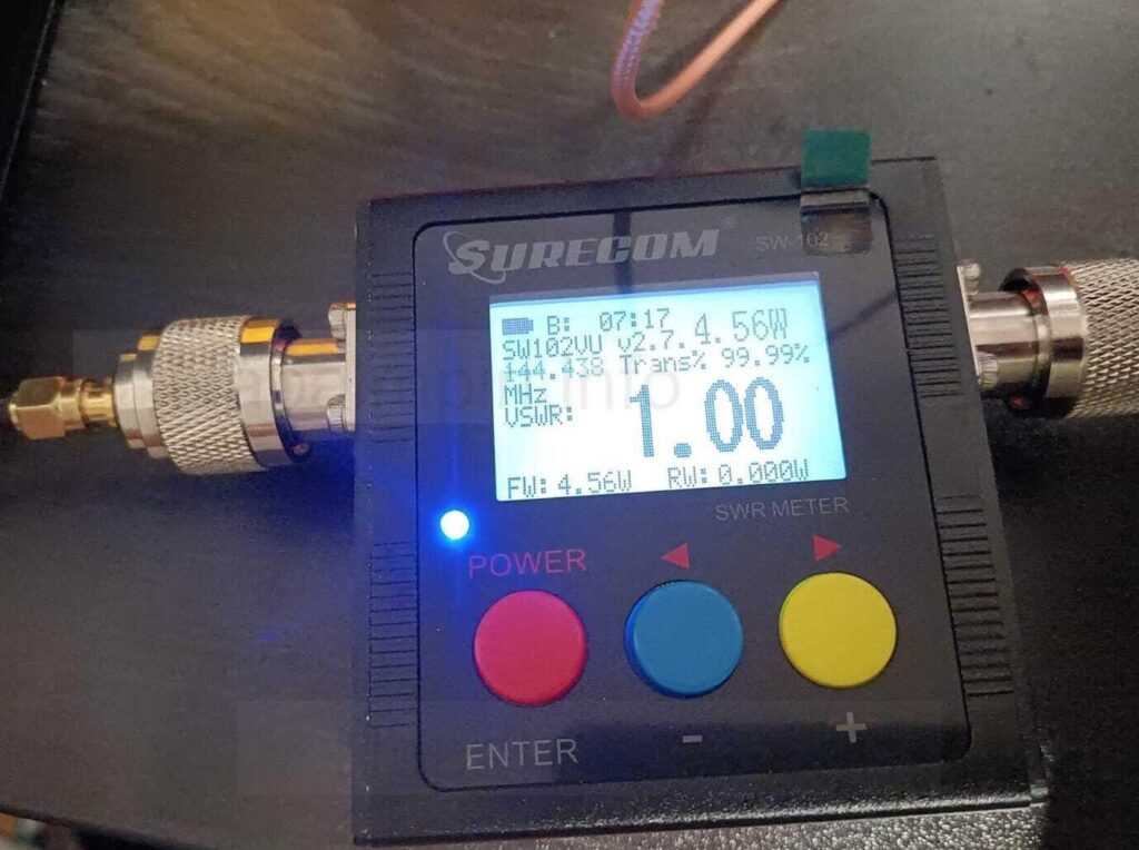
Quick note: all the measurements where made by using a dummy load. A dummy load helps avoid emitting RF during test (and generally speaking makes no sense filter making measurements without a dummy load).
Be gentle with the airwaves, always use a dummy load.
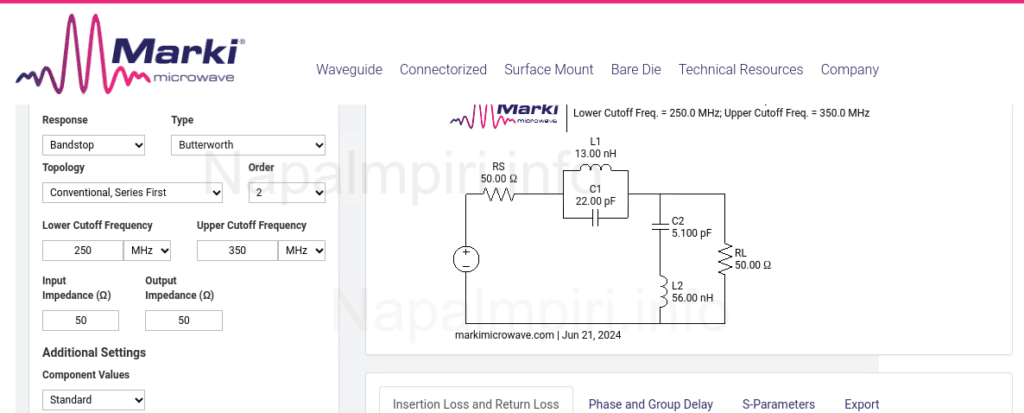
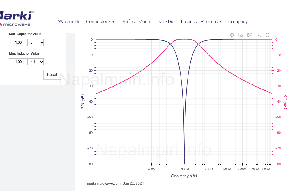
By looking at the harmonics for 144 Mhz I saw a chance to have a bandstop filter and try to filter out the 2nd harmonic and leave out the 3rd which falls inside the 70cm ham band. So i fired out Marki Microwave rf tool and set up to calculate a bandstop for 250 Mhz-350Mhz. I chose Butterworth, 2nd order, conventional series first. By choosing the lower cut frequency (it seems) I was able to damage the 2nd harmonic while leaving the fundamental quite unharmed, and without using higher order filters, with more work to do.
So I set out to prepare the mockup. I first saw this interesting video from @Analogzoo and started building.
I concur with the latter: tuning by inductances is not easy. I use an hard copper wire and deforming the coil is not easy. On the other hand soft wire will move by itself (not good either). Besides, I don’t have a measurement rig for inductance under uH. So I tuned by the capacitors. For this reason at least one of the capacitor values is different from the calculated ones (which is expected, by the way, and by not that much).
For inductances, I used the always handy Coil32 website As in @analogzoo video, I decided to separate the two section with a grounded pcb and to wire the coils in different directions. I opted for an horizontal mounting for sma, and avoided shorcircuiting the center contact by digging a small hole over the pcb.
The filter could be smaller (and a future version it will).
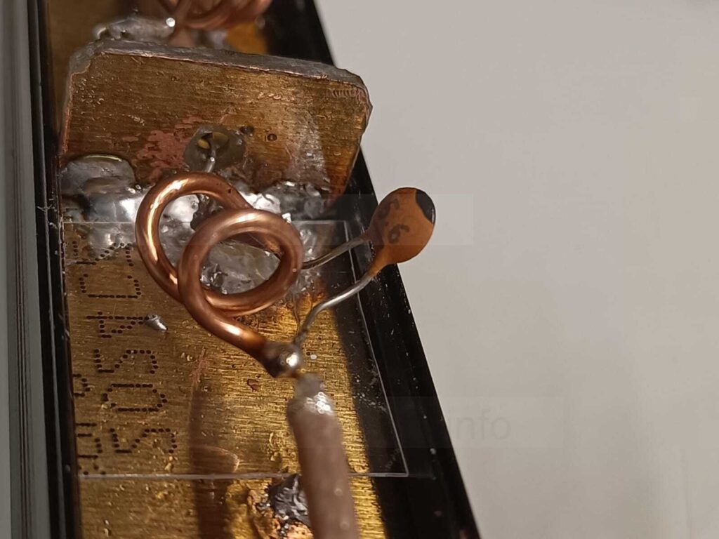
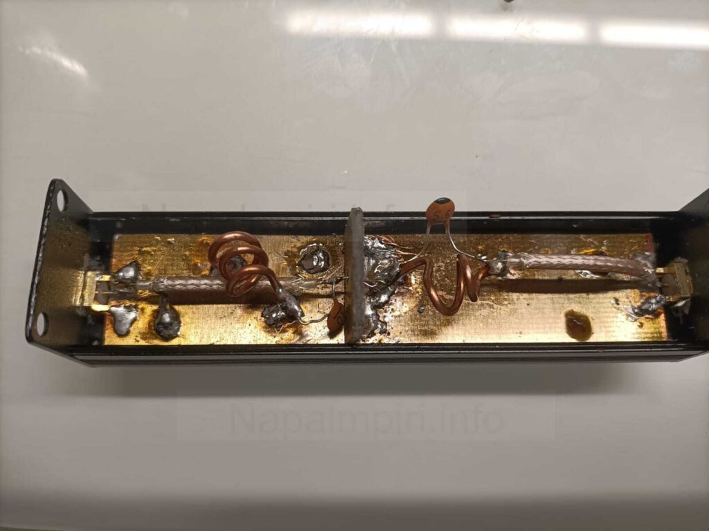
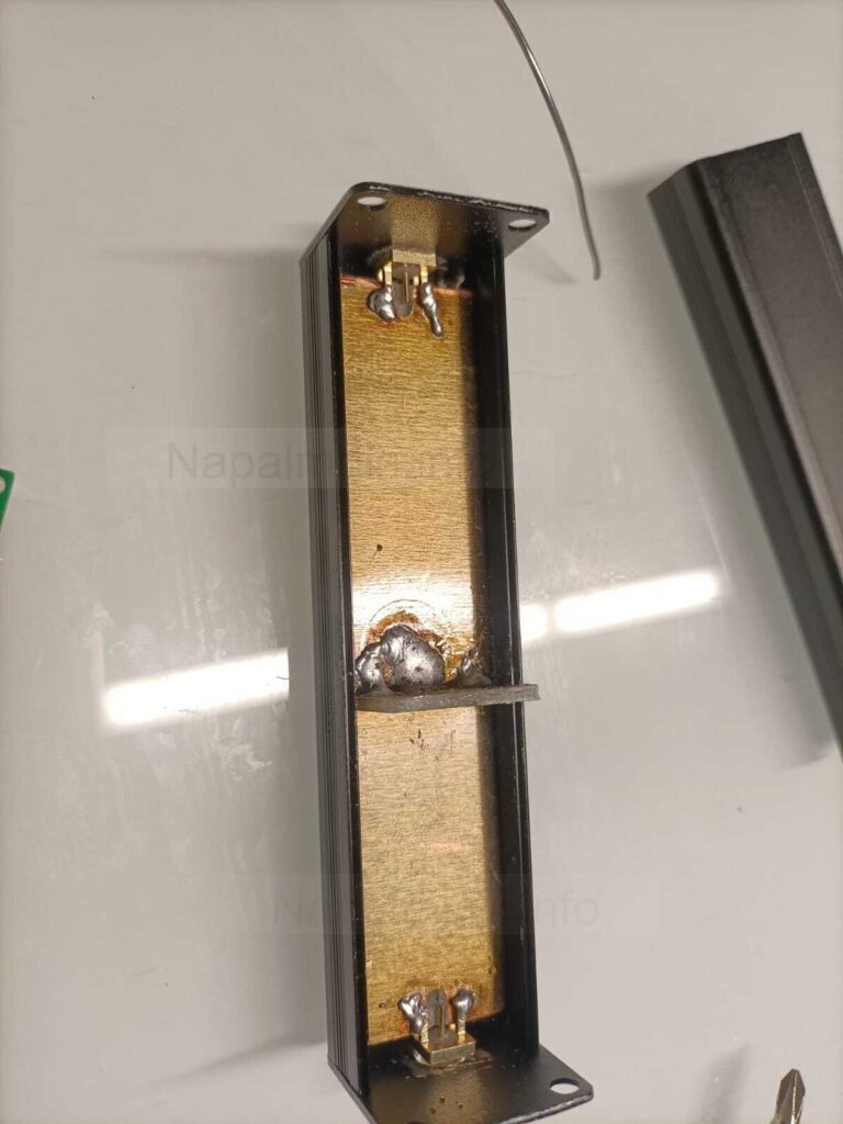
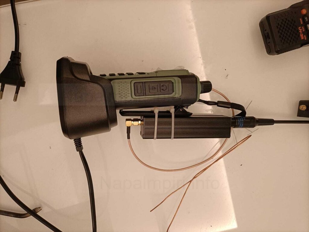
I then stepped in and made the various adjustments, mainly on the first coil (left in the center foto) and capacitor value (10pF instead of 22pF, other values as by schematics. As I cannot measure coils impedance around nH, the coil diameter is 5mm for the coil-former and wire is copper, size is AWG 17. The number of turns is 3 for the input coil and 1.5 for the output coil. The coils are formed clockwise and counter-clowise by design ). The box is Aluminium and it is grounded by scraping the paint from all sides and under the SMA connectors. Measurement made with the box open tend to differ with those made with the box closed, So I had to understand which way the SWR went closing the box, and overshoot the tuning made with the box open. I mainly tweaked the first section for optimal SWR. The PCB is a vetronite-copper , covered in resist. I didn’t bother to scrape off the resist.
By sheer luck I was able to get that 2nd armonic while avoiding damping out too much the fundamental and the 3rd (which again, falls in ham band, where I need to trasmit when I switch band). Soldering is sub-par as I had issues with my solder point, but again, this was a a prototype. Coax cable is Rg174, and that space, in the future, could in principle house something else like a lowpass for the higher armonics. Or maybe not.
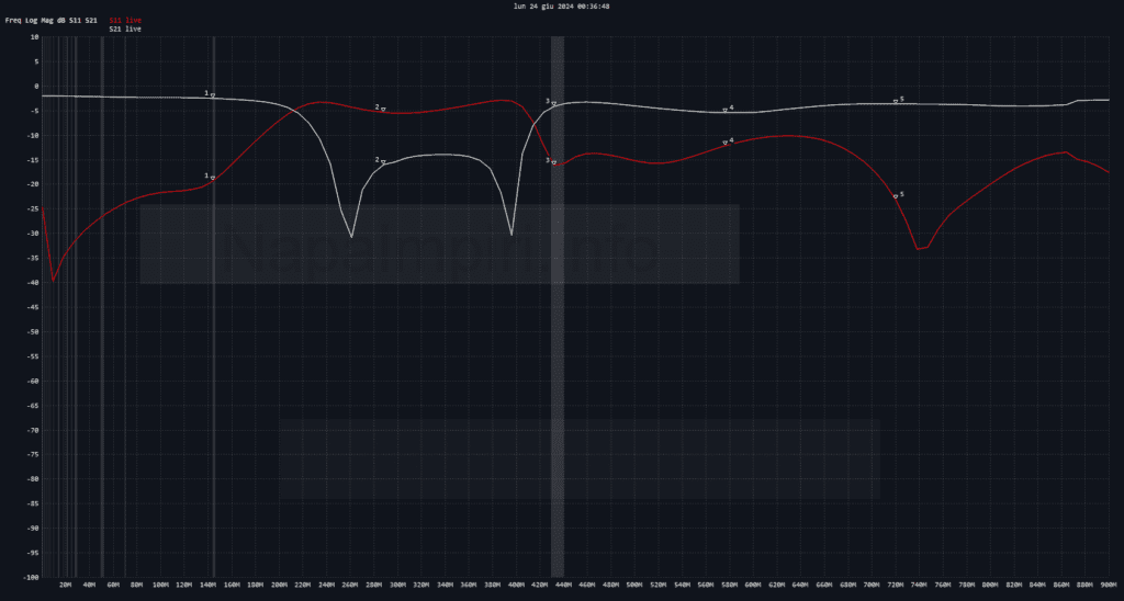
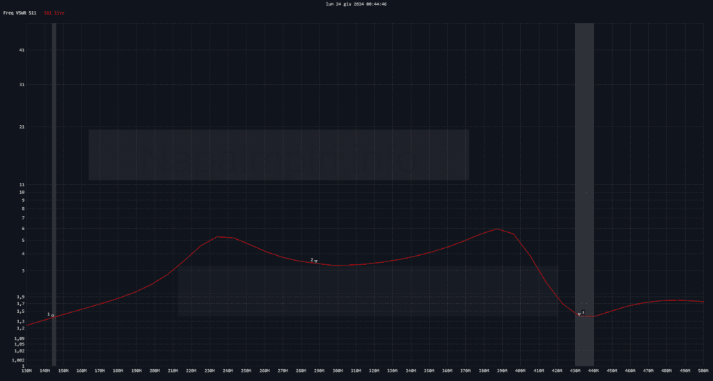
Measurement (sort of) where made with NanoVNA, and my dummy load. As for imput impedance, I saw that measurement with nVNA tended to concur with those made with a rosmeter and my dummy load.
I now plan to make another version of the same, with a smaller container and with the band cut still more over the 2nd armonics.
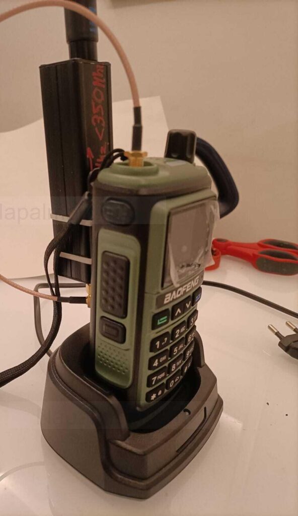
This is the finished version of the filter. It is surely a bit kludgy and unfortunately doesn’t fit on the top because the male connector on the transceiver is too recessed. It is a pity, because with a few mm to spare the box could stand against the transceiver body and avoid mechanically wedging the sma connector directly (which can be an issue with plastic boidies like this). On the other hand I sort like it, considering the style of this specific transceiver. Does it work? I wasn’t able to test it indirectly because my receiver was too close to my test rig with dummy load, but at glance, it seems promising.