I am the proud owner of a modified Quansheng UV-K6 for receving HF…a lot has been said and I won’t bother anyone but I will regroup here a few resources I found useful:
UV-K6
The Hf board I used (mod v.5.0, less modification required…)
The antenna I use
I also needed the programming cable (used one from my Baofeng). here Some tutorials:
OM0ET and TakeApart as well as iu2frl
Some useful tool:
- Flat bar tool to open the device
- Third hand with lens or microscope.
- Good desoldering braid (I didn’t have, I am acquiring it)
- Flux, I used flux for SMD, not the stuff in the jar.
- A soldering tip and solder iron small enough to operate in those little places. Another soldering iron capable to heat up a little more for SMA soldering and ground pad soldering.
- A wrench for SMA (maybe useful)
- very tiny copper wire (how tiny, you will understand opening up the device and seeing what you need to bridge. Be careful that is solder-friendly wire.
- Conical drill bit or various size drill bits..or a small round file to enlarge the LED hole until it fits the SMA connector
The first step for me is always to test the device and be sure that works. Later, it is easier to understand if I broke it or didn’t work in the first place. After that, with the programming cable I use k5prog_win_v1.27 to backup calibration data and initial configuration, saving it for later use.
Modification of ham devices has its risks. Please restrain to do anything unless you want to risk to damage yourself, your properties, or/and violate a bunch of laws. Please note that this device isn’t necessarily free to own and/or use in all countries so I advice you to check independently for local and national laws. In Italy, for example you must have and ham license to operate this sort of devices. Also, the device spots a Lithium battery, so please be careful.
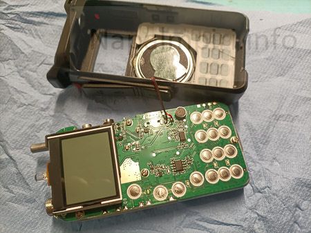
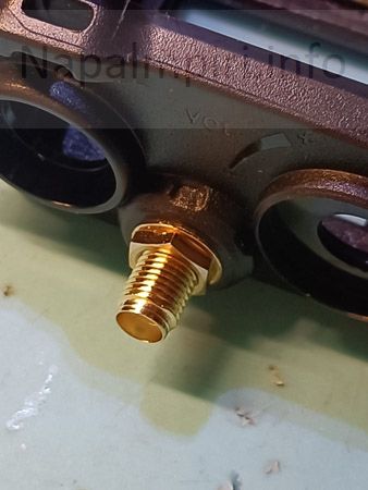
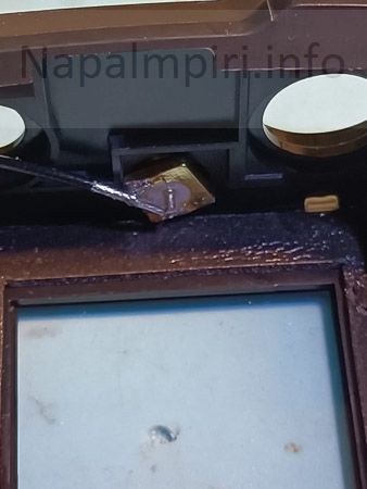
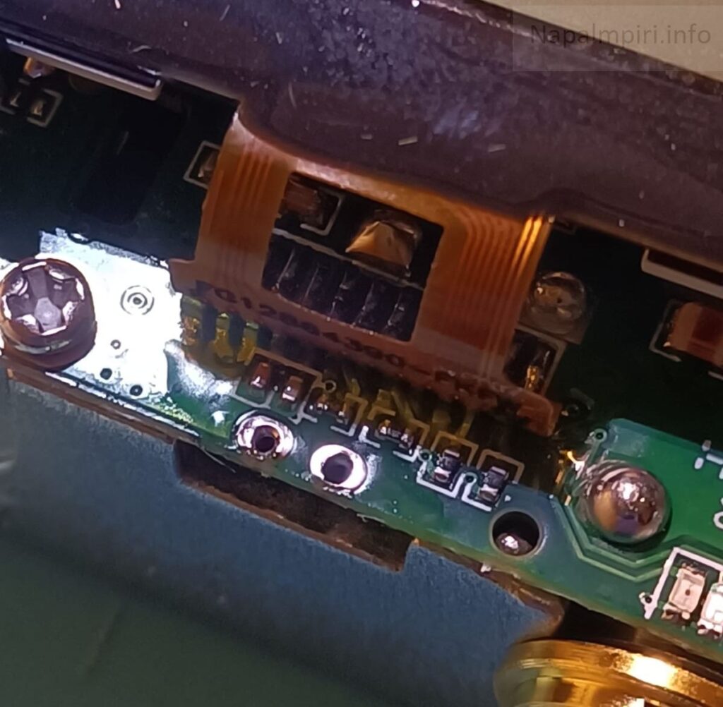
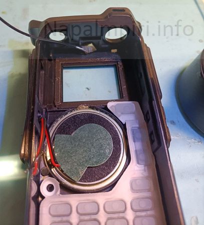
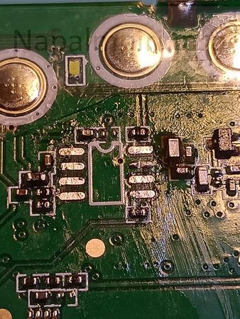
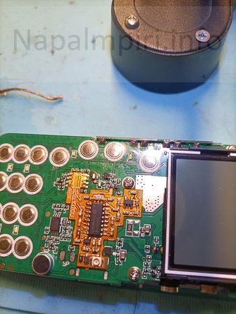
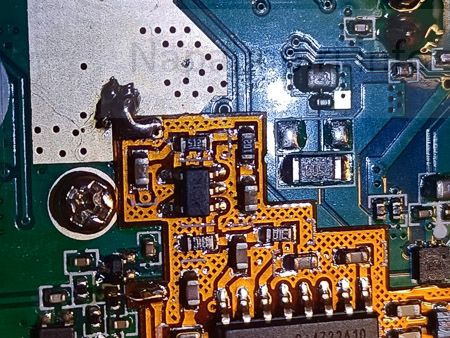
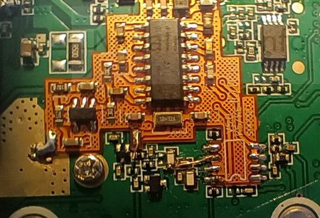
This is the intimidating part.
After this and having soldered the speaker back, the hassle was find a way to route the antenna cable (provided in my bundle, as well as SMA connector and Eeprom), place the speaker and mic cable plastic cover back and close the device.
Please note: The bundle came with the EEprom for 999 Channels. I didn’t do this mod waiting for good solder braid. I then programmed the device using CEC 0.51HF and EZGUMER online UV tools and after powering it up I confirmed the VHF-UHF part was working normally…
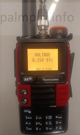
and then long pressed ‘0’. I was greeted by a WAIT message and with an unresponsive device.
BAM. Very disappointed.
I also tried FAGCI reborn and the device didn’t power it up after a brief LCD flash (I then came in the conclusion that this may be a different issue: I am under the impression that FAGCI requires the EEPROM expansion I didn’t dare to do as now without good quality desoldering braid).
After a bit of researching I read the suggestion that the reason for the stuck WAIT message was bad soldering and i2C communication not working. And it was. So I redid the soldering part, flashed CEC again, and tried.
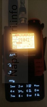
Here it comes another quirk, I wanted to program memories from another unmolested Quansheng using CHIRP, but at first no avail. I then discovered that as one needs a special module for UJV firmware (uvk5_IJV_v2.9R5_jh11i1.py for example) and CHIRP, CEC needs another custom CHIRP module too. I had luck with f4hwn.chirp.driver.v3.9.py and was able to import almost with no error the memories from the other Quansheng over CEC 0.51.
A few random notes or unconfirmed impressions (for myself, mostly):
- The HF mods takes space in memory, so all the CEC whistles like spectrogram and CW-Key with single jack (no double jack) gets unavailable.
- The LED isn’t there, so there will be no effect while putting the device in programming mode (PTT+ Power on). It will simply stay there and wait for flashing…no foretell to say is it even powered on during programming.
- It could be that doing the EEPROM mod is mandatory for flashing FAGCI.
- The HF mod is awesome and I was able to hear morse on 40 meters with that flincky antenna. No issues where noted on receiving and trasmitting on 2m or 70cm.
- I tested the receiver with a trasmitter antenna very near (3m) outputting 8W…Did not overload.
Would I bring this on a gun fight? No. Would I rely on this alone? Given the quality of my work, don’t think so. I would rather bring a backup device with me. But it is freaking to have a single device with full band receiving capabilities and it is a great conversation starter. To soon to say, but for now: Awesome!
.
